

Catastrophic crane boom backwards collapse caused by crane boom recoil from sudden loss of load can be avoided, even if crane boom stops are ineffective, or not fitted. The video below explains the simple calculations needed. These calculations should form part of a Naval Architectural Analysis for a mobile crane mounted on a barge.
Boom Backwards Recoil Collapse in Marine Salvage
Some of the sections from the video are shown below, beginning with an amateur video of a crawler crane boom backwards collapse on a barge during a salvage operation in 2018.
The next clip illustrates the crane boom recoil issue with a 1/12th scale model. In the first part a heavy load is dropped when the model boom stops are not connected. in the second part, the boom stops (which have springs in the model) are connected.
The Excel analysis finds both a closed form analytical solution to the maximum boom recoil angle and also provides a time domain integration of the boom pendant wire sudden tension reduction from the lost load.
The next clip shows the close comparison of the boom pendant wire tension change in the first 0.5 seconds after the load is dropped. Both Excel and OrcaFlex predict that the tension becomes zero after 0.22 seconds. During this time the pendant tension is accelerating the boom’s angular velocity.
The time domain motion of the boom angle is compared in the next clip, then the Excel closed form solutions for a range of dropped load sizes and initial boom angles is shown, for two different pendant wire sizes.
Floating Service Load Chart
A Floating Service Load Chart is required by US Army Corps of Engineers (USACE) Manual EM-385-1-1, Safety and Health Requirements, November 2014, for all mobile cranes mounted on barges, pontoons, etc. This can be provided by the Load Handling Equipment (LHE) manufacturer.
Naval Architectural Analysis
If a manufacturer’s Floating Load Service Chart is not available, a floating service load chart may be developed and provided by a qualified registered engineer or naval architect, competent in the field of floating cranes. STA provides the NAA Service.
Additional Codes and Standards
In developing a Floating Service Load Chart and de-rating any floating crane, the following codes and standards must be considered:
- CFR 173.005: Vessels Equipped to Lift Cargo or Other Loads
- CFR 173.020: Intact Stability Standards
- CFR 1915.115: Hoisting and Hauling Equipment, OSHA
- CFR 1926.1433-1434: Design, Construction and Testing (cranes) OSHA
- CFR 1926.1501(f)&(g), OSHA
- ASME B30.5-2015: Mobile and Locomotive Cranes
- ASME B30.8-2018: Floating Cranes and Floating Derricks
- USACE EM-385-1-1, 2014
- NAVCRANECEN INSTRUCTION 11450.2, March 2013: 2-1.7 Design of Floating Cranes
- NAVFAC P-307, Weight Handling Program Management, 2016
The relevant FRs do not mention crane boom recoil or boom stops. ASME 30.5 specifies that boom stops shall be provided on mobile cranes to resist the boom falling backwards. No design guidelines are given. ASME 30.8 has similar wording. P-307 requires boom stops to be checked, but does not mention precautions to be taken if the crane does not have boom stops. Similarly, EM-385 notes that a crane should have boom stops. NAVCRANECEN Instruction 11450.2 gives a specific analysis to be performed to check if crane boom recoil will result in contact with the boom stops. The load to be used in the analysis is stated with reference to the Floating Service Load Chart.
An example of a Floating Service Load Chart is shown below, with the crane boom recoil limitation on maximum hook loads also included.
An example of a safe lift at a high (77º) boom angle, on a barge mounted mobile crawler crane without boom stops is shown below.
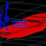
A detailed structural dynamic analysis of the boom and the boom stops can be performed using OrcaFlex, as shown in the next example clip.
SUMMARY
- Calculation of maximum crane boom recoil angle from closed-form analysis equations in Excel
- Calculation of maximum safe loads at high boom angles
- Prevent backwards crane boom recoil accidents
- Time domain “instant” solutions in Excel
- Detailed time domain simulations relatively quick with OrcaFlex
- Structural checks using non-linear dynamic analysis of boom stops and booms performed in OrcaFlex
- Low cost, high value, advanced structural engineering calculations save lives and save money.