
Marine Salvage, Heavy Lift Dynamics
STA performed all time-domain coupled vessel motions analysis of the Sewol salvage in Korea using OrcaFlex. See the blog post on Marine Salvage. See 2017 article in Maritime Executive. Maximum allowable sea states for safe lifting were limited by dynamic sling tensions, hook loads and hull buckling stresses.
A copy of the 2017 technical paper, OTC-27695 Heavy Lift Dynamics, Sewol Ferry Offshore Salvage can be supplied upon request. The Sewol Ferry sank off Korea in 2014 with the loss of 304 lives. The remains of 9 victims remain within wreck and cannot be reached by divers. This paper describes some of the heavy lift engineering involved in the salvage of the 146-meter long ferry, in one piece, from a depth of 44 meters in the ocean, resting on its port side.
A method for calculating the interaction of the vessel stern with the seabed (ground reaction) is described as the bow of the 8,000-ton vessel is raised to place lifting beams to be used in the side lift. Significant difficulties, associated with geotechnical issues, resulting in project delays are described. Calculation methods are presented for determining the large trapped water mass and the large frequency and depth-dependent added mass of the submerged vessel (greater than 120,000 tons). Coupled dynamic time domain simulations of the initial bow lift, followed by the side lift onto a floating vessel are presented. A total of 34 HMPE synthetic slings are used to attach a 1,200-ton purpose-built lifting frame to the ZPMC 12,000-ton revolving crane.
Wave forecast data from three sources are compared with continuously measured data from a directional wave buoy at the site. The difficulties in predicting and controlling the heel of the vessel with a combination of added buoyancy, slings and geotechnical forces are described for the failed attempt at the first bow lift and for the final bow lift. Dynamic sling tensions are shown calculated for the upper HMPE slings and the lower steel rope vertical and balance slings from the lifting frame to the lifting beams. Detailed static and quasi-dynamic FEA results are described for the Sewol hull, together with buckling checks. Please also see the post on the uncertainty of ship stability analysis.

Sewol Side Lift, Partly Emerged. OrcaFlex model, all individual slings included in dynamic simulations.
The main hooks of the ZPMC crane are shown below. The true spread of the HMPE slings inside the hook jaws is not shown, although this spread was accurately accounted for in the detailed analysis models.
Before the side lift, the submerged bow is raised so that lifting beams can be inserted below the hull.
Arrangement of Additional Buoyancy for Bow Lift
The additional buoyancy planned for the bow lift had to be sufficient to enable the bow to be raised without causing structural damage to the hull. The main structural constraints of concern were global and local buckling of the vessel plates and frames. A distribution of buoyancy along the length of the vessel and across the width and height of the vessel was made. The total additional buoyancy and its center were constantly tracked and monitored by diver surveys.
Available Ships Tanks for Air-Filling, Total Useable 1,210t
Air Bags Added Inside Starboard Side on C-Deck and D-Deck, 30t to 54t each (above) and External Buoyancy Pontoons, 500t Steel and 165t to 200t Rubber (below)
Sling arrangement at bow for submerged bow lift, shown above.
Calculating Static Sling Loads from Longitudinal Force Balance
This is a simple calculation, but must assume a location for the longitudinal center of the ground reaction force.
Calculating Static Sling Loads from Transverse Force Balance
This calculation is simplified by assuming no heeling moment is taken by the ground reaction and that the hook loads will resist heeling as the hooks are raised.
OrcaFlex fully coupled dynamic simulation of bow lift is illustrated above. A bespoke seabed soil model is used using non-linear OrcaFlex elements.
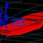
Excel Chart Showing Sections at Frames, and Heel Equilibrium Solution for Second Bow Lift, shown above. Labels indicate vessel frame numbers. Each frame identified is drawn with a different line color in the Excel chart. The frames are shown with the vessel trimmed. Hence Frame 173, in the region where the bow slings attach, appears raised. Frames 0, 6 and -5 are indicated and can be seen to be without any significant seabed contact. The upper short blue arrow indicates the location and magnitude of the combined sling loads. The upper red arrow indicates the location and magnitude of the combined added buoyancy force. The central purple arrow, pointing down, indicates the location and magnitude of the combined weight force. The lower brown arrow indicates the location and magnitude of FG, the ground reaction force. The variable Tpivot, is the transverse distance of FG from the keel. At this distance, FG causes a moment that balances the system such that there is no net heeling moment. The brown trapezoidal area beneath the seabed indicates the reaction pressure that would provide the force FG, if applied over the area of hull calculated to be in contact with the seabed in this load condition. The figure contains a red warning that the soil pressure diagram needs modification following the first bow lift. This is because the vessel heeled (topside going down) during the first bow lift and will have left an indented and disturbed area of soil. Heeling in the same direction would have less resistance from the soil during a second bow lift. Numerous other data are listed on the figure above, enabling the Excel app to be a useful tool to investigate alternative buoyancy arrangements and potential sling alternatives. For example, the soil ultimate bearing capacity used in the above results chart is 50 t/m^2.