
Liftboat Design & Analysis
Find the High Quality Liftboat Design Service Your Organization Needs with STA

The SEWOPS, shown above, is the preliminary liftboat design (2000) of a modified Irish Sea Pioneer (designed by STA) with a 500 ton sheerlegs crane.
STA LIFTBOAT – Dynamic Analysis of Elevated and Afloat Conditions
STA LIFTBOAT is a software package used by designers and also by the US Coast Guard for evaluating liftboat design submissions. View User Manual. The purpose of STA LIFTBOAT is to calculate the structural response and pad reactions of liftboats in the elevated mode, subject to environmental and gravity loads. The program accounts for wind loading on exposed sections of legs in the air gap and above the hull, as well as on the hull and superstructure, including the crane. Wave and current loads are calculated on the legs below the still water level and in the splash zone. Shallow water wave theory is used, as embodied in the ABS MODU Rules and the legs are modeled as equivalent cylinders with the correct equivalent diameter, drag coefficient and inertias which represent the full leg (with rack). The drag coefficient varies with wave attack angle, being strongly influenced by the rack (or racks) on each leg. A graph of drag coefficient with wave attack angle is produced by the program once the user has input the rack geometry.
In order to calculate structural response, the vessel is treated as having a relatively stiff hull. Structural flexibility comes from the legs and the leg/hull connection. Rotational stiffness provided to the pad at the soil structure interface is also modeled. The structural characteristics for each unit to be analyzed are based primarily on the leg structural properties as input by the user. The user may alter the loading condition of the boat, the water depth, the air gap, the amount of pad penetration into the sea bed, and environmental conditions. Additionally, the user may control the stiffness of the pad restraint provided by the soil, by specifying soil strength and a coefficient used by the program to find a soil shear modulus. Alternatively the user may allow the program to calculate the minimum (cohesive) undrained shear strength of the soil necessary to give bearing support to each pad.. The user-specified soil stiffness may be varied from zero, representing a pin joint, through to completely fixed, if desired.
In version 2.0 (and onwards) of the program, the ultimate moment capacity of the soil is reported based upon either the user-specified value for the soil strength, or based upon the minimum soil strength necessary to provide bearing support to the pads. If the user specifies a large degree of fixity at the sea bed, or a rather stiff rotational spring, the program will calculate large moments at the pads. If the calculated moment exceeds the theoretical ultimate moment capacity of the soil beneath the pad the program will issue a warning. In the a future release of the program, the DnV formulae for allowable moments in either sand or clay soils will be used. These maximum allowable moments are a function of the preload applied on each leg and the maximum leg reactions found during the analysis run. In both cases, the program has an iterative solution option which permits the user to maximize the soil stiffness in the analysis to either just meet the ultimate soil moment capacity, or to just satisfy the maximum allowable moment according to the DnV formulae.
Leg stresses typically limit liftboat operational envelopes. STA LIFTBOAT computes unity stress checks based upon both ABS MODU Rules (both pre-1988 and post-1988) and based upon a more rational stress check for slender axially loaded columns, as used by DnV. The US Coast Guard will accept any of these unity stress checks, subject to certain conditions (see User Manual).
© Stewart Technology Associates 1988 and onwards
STA LIFTBOAT also evaluates leg stresses induced by vessel roll and heave motions (plus lateral wind loads) in transit. The user may opt to use standard ABS criteria for MODUS, or use any combination of roll amplitude and natural roll period, or roll amplitude and roll period.
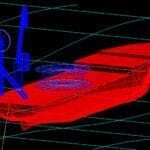
The above figures illustrate some of the wave loading and response calculations undertaken within the program.
The main set of dynamic response results are shown above.
Rational Unity str.chk.legs 1,3
This is the rational stress check used by DnV for jack-up rigs with tubular legs applied to the heaviest loaded of either leg 1 (port) or leg 3 (stbd). The interaction equation for this stress check is given by the maximum of either:
Stress check value = 1.25 {fa/fcr + (fb’ + fb0)/fcr}
Stress check value = 1.25 {fa/fcr + (fb + fb0)/fcr x 1/(1 – P/PE)}
Where:
fb’ is as defined above and includes secondary bending stress components
fa and fb are defined as above (but fb does not include secondary stress components)
fcr = local critical stress
P = average axial leg load due to functional, or self-weight loads, only. (see Note 1, below)
PE = Euler load for leg (using weakest axis)
BM.hull max w/oPD
This is the maximum bending moment found in the legs at their connection with the hull during a wave cycle, before P-delta effects and dynamics are applied. In other words, it is the bending moment that would be found for a structure without any deflections.
The safety factor of 1.25 is equivalent to making the unfactored interaction equation equal to a maximum “usage factor” of 0.80, appropriate for design storm loading.
fcr is determined from the yield criterion (see Note 2, below) as:
fcr = (fx/fe) f
Where:
fx = actual value of axial stress component in the leg
fe = von Mises equivalent stress component.
fY = yield stress of leg steel
In practice the von Mises stress is almost identical to the axial stress component, as shear stress is small (and in any case, the point of maximum shear stress is at 90 degrees around the leg circumference from the point of maximum bending stress). Consequently the critical stress, fcr, is generally approximately equal to the leg yield stress.
BM.hull max. w/PD
This is the maximum leg bending moment computed at the hull connection, including all response effects. See User Manual for more details.
Pad Ultimate Moment Capacity
This is the calculated ultimate moment that the soil can apply to the pad, based upon a cohesive soil, an circular pad of equivalent area to the actual rectangular pad, and a hemispherical failure surface with the same radius as the equivalent circular pad. The center of rotation is assumed at the pad center and the soil shear strength is assumed to increase beneath the pad at 4 psf/ft of depth. If this maximum calculated moment at the pad exceeds this value, a warning is printed at the top of the Results Summary.
In the Version 4.0 STA LIFTBOAT program, this ultimate moment is no longer used and the methodology described in the 1997 City University Jack-Up Conference paper by Stewart is now implemented.
View the STA Liftboat User Manual.
If you are in need of high quality professional marine or offshore engineering services, be sure to contact Stewart Technology Associates for unrivaled excellence and experience, especially in the case of liftboat analysis and design review.
Stewart Technology Associates will work closely with your organization in order to satisfy your specific requirements perfectly. When it comes to liftboats and liftboat design, you will make the right choice if you decide to work with Stewart Technology Associates, as we provide a range of services related to liftboats which can include design inspection which ensures that liftboats are safe and properly in place when stationed. With the help of special propriety software, Stewart Technology Associates will deliver unparalleled design and design analysis, which will surely provide your organization with what it needs to reach specific goals. Our software also enables Stewart Technology Associates to assist both public and private organizations with a range of other high quality professional services, which include jack-up analysis, pipe lay analysis, anchor analysis, riser analysis, and many more.
Find efficiency and cost-effectiveness with Stewart Technology Associates! Since Stewart Technology Associates has been providing marine and offshore engineering services for more than 20 years, we certainly have the experience that your organization needs to accomplish its goals. Our company and service structure is set up so that we can provide you with a great deal of efficiency, and it’s also important to point out that our company is purposefully small so that we can assist our customers with the absolute highest amount of quality and dedication. Needless to say, with Stewart Technology Associates, you will find a dedicated partner who will be able to provide you with expert liftboat design or other marine and offshore engineering services that you are in need of.
No matter your specific liftboat design requirements, Stewart Technology Associates will be able to fulfill your requests. Please browse through the rest of our website in order to find out more about our professional marine and offshore engineering consultancy services, and if you would like to move forward with a specific service or have any questions, then don’t hesitate to contact Stewart Technology Associates directly by either phone or email. We will be looking forward to working with you!