
Pile Anchors – STA PILE3 Program
STA PILE3 is a commercially available computer program developed by STA, for the design and analysis of pile anchors. STA PILE3 deals with suction anchors and driven anchors. Click here for a copy of the USER MANUAL. Bil Stewart originally developed this program for in-house use, but was asked by clients to make it available commercially.

Simple Input Data
The simple input and control data is shown in the figure above. Note that the padeye may be buried at any depth down the pile, which may itself be buried or have a length standing above the seabed. A detailed description of the program is given in the User Manual.
In addition to analyzing the capacity of installed piles, STA PILE 3 may be used to calculate the conditions associated with the installation of suction embedded piles. Suction embedded piles are installed by causing a differential pressure between the inside of the pile and the surrounding water. This differential pressure causes a net downwards force on the top of the pile. Under certain conditions, the pile will force itself into the sea bed.
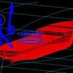
General Failure Mechanism
The general failure mechanism assumed by the program is for the pile to rotate about some point within its length as a consequence of the lateral load or to pull upwards as a consequence of the vertical component of load applied to the pile.
The diagram above,shows the basic failure mechanisms considered in STA PILE.Horizontal capacity is governed by rotational failure, as shown below. Vertical uplift capacity (or embedment resistance) is calculated. Suction embedment may be specified, in which case the program computes necessary suction pressure differential. All piles must satisfy the criteria for”short stiff” piles.
In the case for a vertical pile unrestrained at the head subjected to a lateral load at the pile head, the lateral loading is initially carried by the soil close to the ground surface. As the load at the pile head is increased, the soil compresses elastically, but the movement is sufficient to transfer some pressure from the pile to the soil at greater depth. Eventually, the soil yields plastically, and transfers loads to greater depth still. This program is for short “rigid” piles. Length to width ratios should be less than 12. At the ultimate capacity load (applied horizontally to the pile head) the pile will rotate and fail the soil plastically. A passive resistance develops above the toe on the opposite face of the pile adding to the resistance of the soil further up the pile towards the ground surface. Failure occurs when the passive resistance of the soil at the head and the toe are exceeded.
The method of Brinch Hansen is used to calculate the ultimate lateral resistance of the pile, inasmuch as the pile is divided into around 50 elemental lengths. This number varies depending upon whether the pile is completely buried or has any of its length above the soil. Each elemental length is treated as a rigid unit. The maximum passive resistance for each rigid unit, however, is not found using Brinch Hansen’s coefficients, but is found using API coefficients.
Layered Soils
Up to three soil layers which may be mixed cohesive and cohesionless layers can be specified by the user in STA PILE3. In each layer, the above equations are implemented for each elemental length of the pile. Overburden pressure is calculated for buried cohesionless layers.
Rotational Failure Calculations
In order to calculate the failure mode of a pile anchor subject to horizontal loading, the unit passive resistance of each element of the pile at a depth Z below the ground surface is given by the equation:
Pz = PozKqz + cKcz
Where Poz is the effective overburden pressure at depth z, c is the cohesion of the soil at depth z, and Kqz and Kcz are the passive pressure coefficients for the frictional and cohesive components respectively at depth z.
For each successive soil layer, the depth z is assumed to begin at the top of the soil layer in order to determine the appropriate coefficient Kq or Kc. However, the effective overburden pressure is calculated from the top of the soil down to the depth of the layer in question.
The total passive resistance on each horizontal element (dH) is given by the equation:
dH = pzdHB
The point of rotation of the pile is then found such that the summation of the passive soil resistance forces times their lever arms above the point of rotation balances the sum of the element passive resistances multiplied by their lever arms below the point of rotation.
Having found the depth to the center of rotation from the above approach, the ultimate lateral resistance of the pile to a horizontal force is obtained by taking moments about that point of rotation. The program then constructs shearing force and bending moment diagrams. The bending moments, shear forces, and soil reaction diagrams are reported on the single page of output which would normally be printed by a user of the program.
Internal and External Friction
If the vertical component of loading applied to the pile is upwards, shaft friction on the outside of the pile only is considered. However, if the vertical loading is downwards, STA PILE3 considers internal shaft friction if the pile is specified as open ended, or the end bearing of the plug, whichever is less, as well as the end bearing of the pile wall annulus. If the pile is specified as closed end, the end bearing of the full cross section is calculated. The equations for end bearing are taken from API RP 2A with coefficients and limiting values from Table 6.4.3-1.
The user of STA PILE3 is cautioned to use care in selecting the soil properties for analysis.
The user can see a graph of skin friction down the pile by clicking once on the “Friction” button. An example is shown in the figure below.
Pile Stresses
Having found the bending moments in the pile, the program calculates bending stresses and reports the maximum bending stress in response to the ultimate horizontal load that the pile can resist. The program also reports the bending stress in response to the user specified applied horizontal load.
Additionally, the program reports axial stresses in response to the vertical loads. The program determines the ultimate vertical (upwards) load that the pile can carry and the maximum axial stress that this will cause. It reports this value as well as the maximum axial stress in response to the user specified vertical load, as shown below.
STA PILE3 COMPARISON with Other Software
In 2011, a technical comparison of STA PILE 3 with Agspanc was made for Saipem, for a Submarine Pipeline Start-Up Suction Pile. View full Technical Note.
A 3-layer soil profile was modelled in the analysis, involving cohesive soil with low uniform strength in the first layer. Than a layer of increasing strength with depth down to 4.0 meters. A lower strength clay lay below the second layer, resulting in the shear strength profile shown in the figure above.
Consultancy and Expert Testimony
When searching for a trusted name in expert witness marine services, look no further than Stewart Technology Associates. With our services, no matter the specific offshore engineering failure, we will be able to accurately analyze it in order to determine the specific cause or causes, and if necessary, solutions so that these failures will not occur again in the future, and in the case of analyzing pile anchors, there is no better firm than STA. Stewart Technology Associates has built its reputation on being absolutely dedicated to providing its clients with the most accurate and highest quality analysis possible, and this is especially the case with regard to pile anchors.
These anchors are one of the most widely used in offshore structures, and although similar to conventional piles, they carry the load differently, transferring tensile forces from floating objects to the sea bed. Whenever an organization has a serious problem with one of these anchors, they can certainly rely on the knowledge and experience of Stewart Technology Associates in order to have the problem correctly analyzed and solved in an efficient and cost-effective manner.
Founded in 1986
Stewart Technology Associates has been in business for over three decades, and during this time, we have built up a fantastic reputation of helping our clients in a range of marine and offshore engineering consultancy areas, from wave power system design and analysis to expert witness marine services. Our company is made up of bright and motivated professionals who have many years of relevant marine engineering experience, and with the vision of our CEO, Bil Stewart, PE, we’ve managed to sustain our success over the years. We’ve built up an impressive list of clients over the decades, including major oil companies, oil services companies, government agencies, and large financial institutions. Needless to say, we are able to assist virtually any organization, large or small, with pile anchors or other specific marine and offshore engineering consultancy service.
Take the time to find out more about Stewart Technology Associates today! Within our website, you’ll have the opportunity to get acquainted with our company and its successful history, our services and capabilities, and our preferred software, Orcaflex by Orcina. If you have any questions or are interested in pile anchors service or another specific offshore engineering consultancy service, then don’t hesitate to contact Stewart Technology Associates directly by phone or email.